Before you begin
A lid can look accurate and still refuse to close. The dimension that matters is the space between the actual mating surfaces after printing and finishing. A rounded corner, a seam bump, or a slightly widened first layer may control assembly more than the outside size measured across the middle of the part.
This guide treats fit as a small engineering experiment. Define the motion or retention you need, print a representative joint, measure its behavior, and repeat the successful process. The example dimensions below illustrate the arithmetic and test method; they are not recommended clearances for every printer, material, or joint.
Describe a successful assembly
Start with a sentence that can be tested: the lid must slide on by hand, sit flush, and remain removable without tools. A different project might require a shaft to rotate freely without excessive wobble. These statements identify what must be measured. A tight joint is not automatically a good joint if it cracks during assembly or becomes impossible to service.
Clearance fits leave space between mating features. Interference fits deliberately overlap their nominal sizes and rely on deformation or assembly force. Transition fits sit between those outcomes. Do not choose interference merely because a friction fit sounds secure; wall thickness, material flexibility, contact length, and repeated use all affect the result. Decide separately which faces locate the part and which feature holds it in place.
Calculate the gap you actually mean
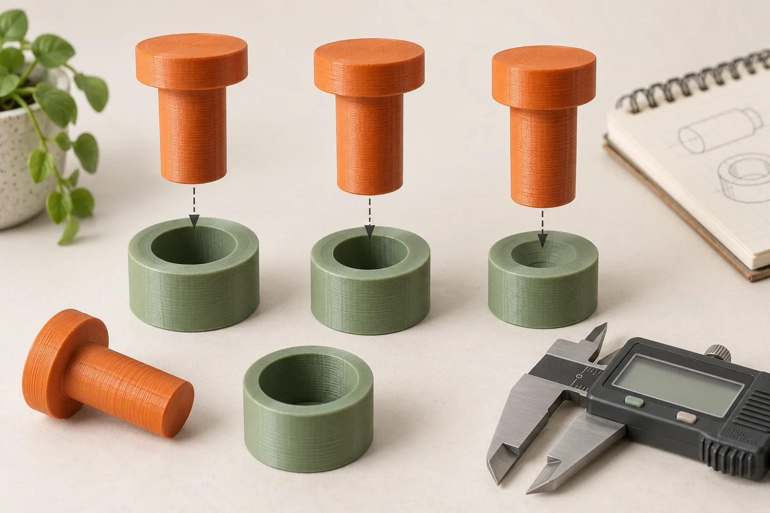
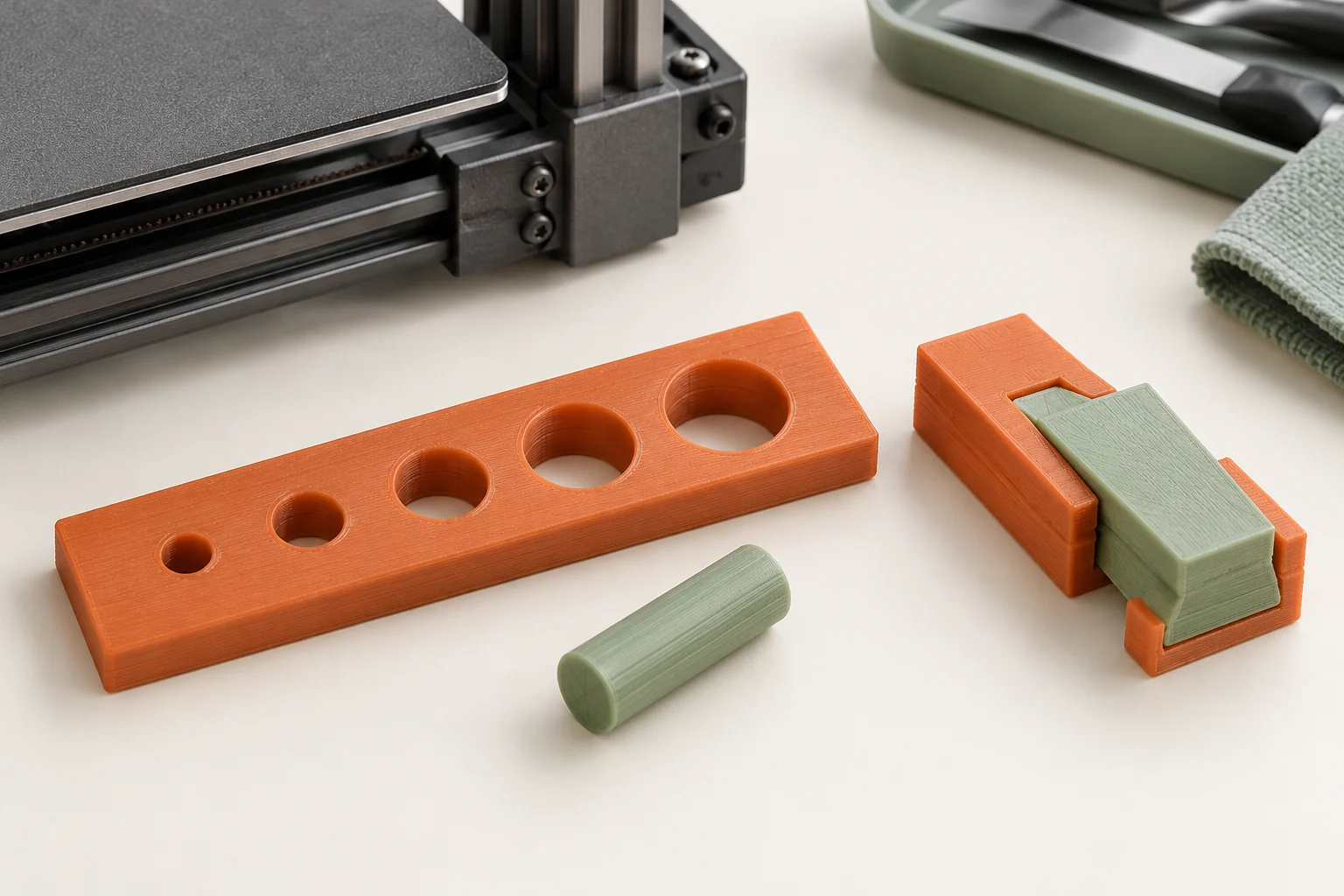
For a round pin and hole, diametral clearance equals hole diameter minus pin diameter. In a centered assembly, radial clearance is half that difference. An illustrative 10.00 mm pin in a 10.40 mm hole has 0.40 mm total diametral clearance and 0.20 mm clearance on each side. Calling either quantity simply 'the tolerance' invites a factor-of-two mistake.
A rectangular tongue follows the same subtraction across its width, but its height and insertion length are separate constraints. If a tongue enters easily and then jams, increasing width clearance alone might miss an obstruction at the end, a tapered wall, or a bowed slot. Sketch a cross-section and label every independent gap before editing CAD. Record units explicitly when transferring dimensions from sketches or downloaded models.
| Quantity | Illustrative value | Meaning |
|---|---|---|
| Pin diameter | 10.00 mm | Nominal size of the inserted feature |
| Hole diameter | 10.40 mm | Nominal size of the receiving feature |
| Diametral clearance | 0.40 mm | Hole minus pin |
| Radial clearance | 0.20 mm | Gap per side when centered |
Separate design clearance from manufacturing variation
A design can contain a gap while the printed assembly has none. Suppose a test hole measures 10.22 mm and its intended 10.00 mm pin measures 10.12 mm. The measured clearance is only 0.10 mm, even though the CAD example allowed 0.40 mm. That observation tells you to inspect both members; it does not establish a universal correction for the printer.
Repeatability matters as much as the average. In a deliberately simplified worst-case example, a hole specified as 10.40 ± 0.10 mm and a pin as 10.00 ± 0.10 mm would have a minimum diametral clearance of 10.30 − 10.10 = 0.20 mm. Those assumed limits must come from an actual requirement or measured process, not a printer's layer-height specification. Resolution describes a different property from dimensional accuracy.
Build a coupon that preserves the real joint
A useful coupon is a short, inexpensive section of your design containing its actual mating geometry. Keep the production material, nozzle, layer settings, orientation, wall structure around the joint, and planned finishing. A vertical hole test does not automatically predict a horizontal hole supported during printing. A short loose ring also cannot fully represent a long sleeve that contacts a shaft along its entire length.
Make a labeled series rather than editing randomly. For example, compare three receiving widths separated by a deliberately chosen CAD increment, while keeping the tongue identical. Include a little extra range around the expected fit so the test can reveal both loose and tight outcomes. Labels should sit away from contact surfaces. Save the coupon project alongside the eventual assembly so the reason for the selected dimension remains visible.
- Mark the mating surfaces and insertion direction in a sketch.
- Extract a short section that retains nearby walls and corners.
- Change one dimension across clearly labeled variants.
- Inspect every variant in the sliced preview before printing.
Diagnose where contact occurs
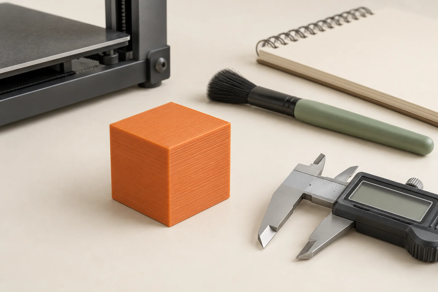
Inspect the point where assembly stops. A bright rubbed stripe or a snag at one corner can reveal a local obstruction that a single caliper reading misses. Compare the base, middle, and upper region of the feature. Measure in more than one direction where the geometry permits, using gentle, consistent measuring pressure so a thin wall is not squeezed into a misleading result.
First-layer expansion, often called elephant foot, deserves a separate check. Slicer compensation can reduce the first-layer outline, but that is a local correction. Scaling the whole model to remove a lip also changes holes, screw spacing, and every other dimension. Confirm that an apparent bottom-edge problem is actually confined to that region before changing the relevant compensation or adding a lead-in chamfer.
| Observed behavior | Possible explanation | Useful next check |
|---|---|---|
| Starts only after trimming the base lip | First-layer expansion | Compare dimensions above the bottom layers |
| Binds in one direction | Local shape or orientation effect | Measure across two directions |
| Fits briefly, then jams | Long contact, taper, or debris | Inspect the full insertion path |
| Every coupon behaves differently | Unstable process or measurement | Repeat the same coupon before redesigning |
Make assembly easier without losing location
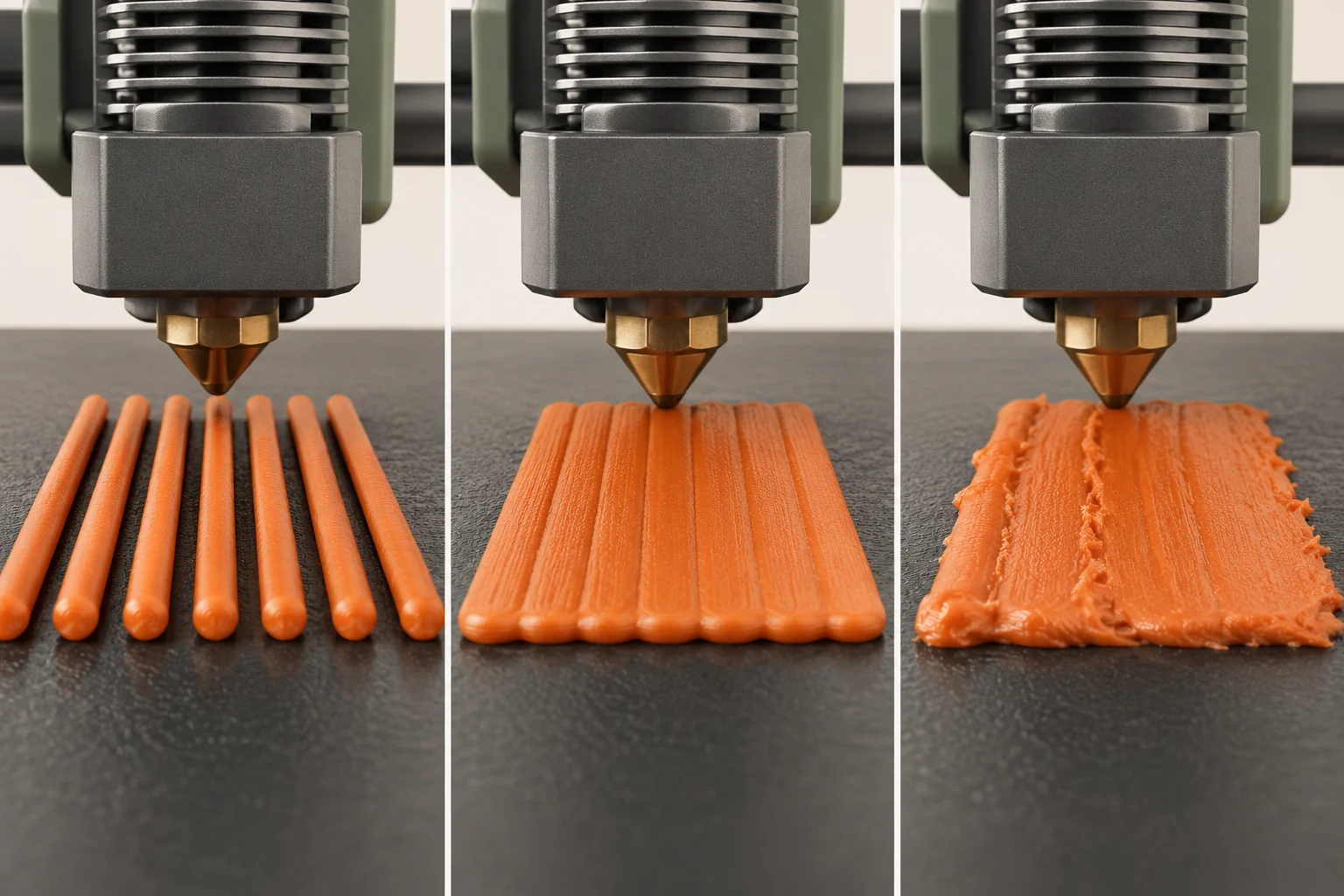
A small lead-in chamfer guides the two parts toward alignment. It does not create clearance deeper inside the joint, so a generous entry can conceal a tight interior during the first few millimeters of assembly. Keep a distinct locating surface beyond the entry, and test whether the joint seats completely. If a mating face needs support, consider whether a different orientation or a split design would preserve that surface better.
Our suggested enclosure trial uses a lid corner coupon first, then a longer edge section, and finally the whole perimeter. The corner trial reveals local interference; the longer section adds contact length; the full lid exposes distortion and the accumulation of several constraints. This sequence saves material while avoiding the false conclusion that one easy-fitting corner guarantees an entire rectangular lid will close.
Confirm the finished part and preserve the result
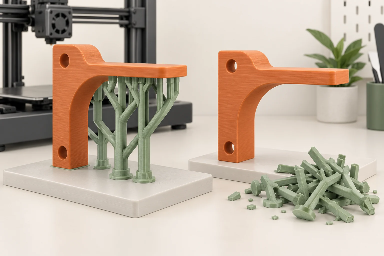
Evaluate parts after their normal cooling and finishing steps. For resin, include the prescribed wash and cure before making a final judgment; for other processes, include any planned sanding, coating, or conditioning. Use the actual mating hardware when possible. An ideal CAD shaft and a purchased shaft with its own dimensional limits are different test partners.
Print more than one copy of the selected coupon and record the range of results, not just the best one. Then test the real assembly through the required insertion, removal, and motion cycles. Our suggested record includes nominal dimensions, measured dimensions, orientation, material batch, profile, finishing, and a short description such as 'slides fully with light hand pressure.' Recheck after a material, nozzle, orientation, or process change.
Common questions
What clearance should I use for every moving part?
There is no dependable universal value. Start from relevant manufacturer guidance, then test the actual geometry and process. A short hinge, a long sliding rail, and a removable lid impose different contact and alignment requirements.
Should I resize the entire model until the hole fits?
Only when evidence supports a global scale error. A local hole problem or a widened first layer is better investigated locally. Whole-model scaling also changes mounting distances, wall thicknesses, and other features that may already be correct.
Why does the same design fit differently after a material change?
The process has changed. Material behavior, required print conditions, surface finish, and finishing can all affect the mating surfaces. Keep the old result as a reference, then repeat the coupon test with the new material.
Continue with the sources
- How to Optimize 3D Printing Tolerances for Engineering Fits Formlabs · Checked 2026-10-15
- Modeling with 3D printing in mind Prusa Research · Checked 2026-10-15
- Guide to 3D Printing Tolerances, Accuracy, and Precision Formlabs · Checked 2026-10-16
- Elephant foot compensation Prusa Research · Checked 2026-10-16
This guide synthesizes the cited references and includes illustrative examples, not hands-on test results. Follow the instructions for your exact printer, material, and software version. Generated illustrations simplify geometry and equipment; they are not photographs, measured results, or model-specific setup instructions.